Self-Assessment Framework
| Part of | Uniplanar External Fixation |
|---|
This module allows medical officers, junior orthopedic surgery residents, and surgeons who are not orthopedic specialists to become confident and competent in irrigation and debridement, powered and manual drilling, positioning and correctly inserting Schanz screws, and constructing the uniplanar external fixator frame as part of external fixation procedures for open tibial shaft fractures performed in regions without specialist coverage. To maximize patient safety, this module teaches learners to use a powered drill to insert self-drilling Schanz screws through the near cortex and then manually advance Schanz screws into the far cortex to avoid plunging.
Self-Assessment Framework
After the reduced fracture has been stabilized with the uniplanar external fixator, please follow the 6 steps below, use the learner's cellphone to take 5 post-operative photos ("digital X-rays"), and fill out the Training Logbook.
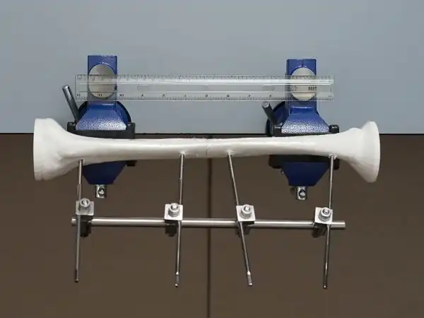
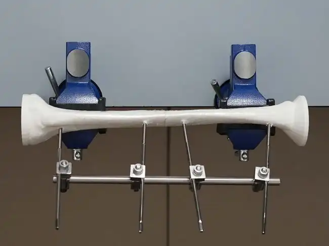
1. Take an anterior view photo of the simulator with a ruler in the image to provide scale.
2. Visually inspect the tibial shaft and confirm that the alignment is within acceptable parameters:
Bone apposition > 50%
Rotation < 10 degrees
Angulation < 10 degrees in the coronal plane.
3. Use the ruler to measure the distance of the 2 "near" Schanz screws from the fracture line:
2 "near" Schanz screws were placed at least 2.0 cm (a finger breadth) from the fracture line to help prevent the placement of the Schanz screw within the fracture hematoma and reduce the risk of having a pin site infection spread within the fracture.
4. Visually inspect the fracture line to confirm that the reduction is adequate:
length discrepancy ≤ 2 cm shortening
no distraction (lengthening).
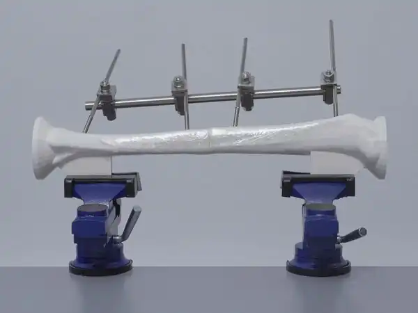
- Take a medial view photo of the simulator.
- Verify the "far" Schanz screw in the proximal fragment was inserted medial or distal to the tibial tuberosity to avoid tethering of the patellar ligament and penetration into the knee joint.
- Confirm all 4 Schanz screws were inserted medial to the tibial crest in the medial photo to reduce the risk of thermal osteonecrosis and reduce the risk that the screw tip may slip and injure the soft tissues.
1. Take a lateral view photo of the simulator.
2. Verify that all 4 Schanz screws in the lateral photo did not perforate the far cortex to avoid injuring underlying soft tissues.
3. Visually inspect the tibial crest in the lateral photo and confirm that alignment is within acceptable parameters:
Bone apposition > 50%
Rotation < 10 degrees
Angulation < 10 degrees in the saggital plane.
- Remove the rods and clamps but leave the 4 Schanz screws in the distal and proximal fragments.
- Use scissors to cut the cellophane wrap overlying the fracture site to separate the 2 fragments.
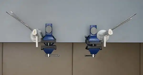
- Remove each fragment from the vise clamp and place each fragment on a flat surface for inspection of the drill trajectory angles.
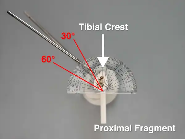
- Place a protractor on the cross-section of the proximal fragment and line up the center vertical black line of the protractor with the center of the vise attachment.
- Take an overhead ("bird's eye view") photo of the cross-section of the proximal fragment to record the drill trajectory angles relative to the tibial crest and verify that the center vertical black line of the protractor is lined up with the center of the vise attachment in the overhead photo.
- For the proximal fragment, the drill trajectory angles of both Schanz screws should be identical and between 30°-60° relative to the tibial crest to avoid injury to neurovascular structures.
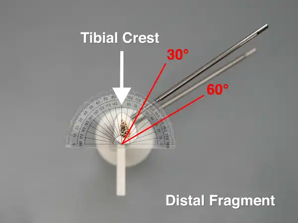
- Place a protractor on the cross-section of the distal fragment and line up the center vertical black line of the protractor with the center of the vise attachment.
- Take an overhead ("bird's eye view") photo of the cross-section of the distal fragment to record the drill trajectory angles relative to the tibial crest and verify that the center vertical black line of the protractor is lined up with the center of the vise attachment in the overhead photo.
- For the distal fragment, the drill trajectory angles of both Schanz screws should be identical and between 30°-60° relative to the tibial crest to avoid injury to neurovascular structures.
- The drill trajectory angles of the 4 Schanz screws inserted into the proximal and distal fragments are identical.
Acknowledgements
This work is funded by a grant from the Intuitive Foundation. Any research, findings, conclusions, or recommendations expressed in this work are those of the author(s), and not of the Intuitive Foundation.
| Authors | Medical Makers, Habila Umaru |
|---|---|
| License | CC-BY-SA-4.0 |
| Organizations | Medical Makers |
| Cite as | Medical Makers, Habila Umaru (2022–2025). "Uniplanar External Fixation/Self-Assessment Framework". Appropedia. Retrieved November 28, 2025. |